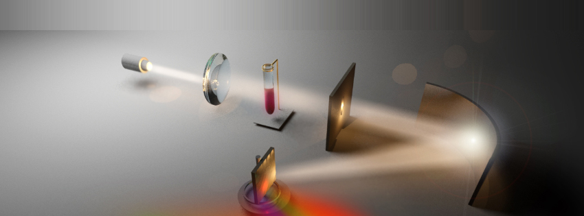
The Detector
In every spectrometer, regardless of design, the final element in the optical system is some form of photodetector. A photodetector is a device that absorbs the optical energy and converts it into electrical energy, either in the form of a current (photodiodes, for example) that flows out of the photodetector or in the form of stored charge that is transferred to a readout circuit (CCD, for example). The electrical current generated or the charge stored is proportional to the incident optical power by a characteristic constant of the photodetector. The processing electronics and software of the spectrometer use the constant to translate the electrical signals back into optical power for display and data storage purposes.
The type of photodetector used in a given spectrometer depends on the method used for performing the wavelength-by-wavelength analysis.
Rotating Grating Method: The rotating grating method uses a single, small-area photodetector, commonly referred to as a point detector. As the grating rotates, the electrical signal from the detector varies with the amplitude of the incident optical power and changes in the proportionality constant for each wavelength directed to the detector. The processing elements assign a wavelength to the electrical signal based on the current angular position of the diffraction grating.
Detector Array Method: The detector array method uses a regular array of photodetectors, with one axis of the array aligned along the direction of linear dispersion from the diffraction grating. In an array with only one row, each detector in the array captures a small range of the wavelengths from the grating. In an array with multiple rows, such as a CCD detector array, each column captures a small range of wavelengths from the grating. The electronic processing elements then translate the electrical signal from each column into a power associated with the wavelength range, as determined in the design and calibration of the spectrometer.
DLP-Based Method: The DLP-based method uses a large area point detector. The DMD directs small ranges of wavelengths toward the detector, and collecting optics ensure that most or all of the optical power falls within the area of the detector. The electronic processing elements associate the electrical signal from the detector to a wavelength range based on the column of mirrors activated on the DMD. The design and calibration of the spectrometer determines which mirror columns correspond to which wavelengths.
Detector Parameters: Wavelength Range
One of the most important parameters of a photodetector is the range of wavelengths over which the detector produces an electrical signal in response to incident optical power. Spectrometers typically use semiconductor-based photodiodes, either based on silicon (Si) or indium-gallium-arsenide (InGaAs). The bandgap energy Eg of semiconductors, defined as the minimum energy an electron within the semiconductor must absorb from the light to contribute to the current or charge produced by the detector, determines the largest wavelength λmax that the semiconductor can absorb, according to the relationship
λmax = hc/qEg
where h is Planck’s constant (6.63·10-34 J·s), c is the speed of light (3·108 m/s), Eg is the gap energy in eV, and q = 1.602·10-19 J/eV. Silicon has a bandgap energy of 1.11 eV which corresponds to a maximum wavelength of approximately 1117 nm. Thus, silicon-based photodetectors are primarily used in visible light spectroscopy applications or for applications using NIR light below 1 µm. Alloys of InGaAs are constructed by mixing InAs and GaAs in varying proportions, resulting in Eg values that range from 0.36 eV (pure InAs) to 1.43 eV (pure GaAs), corresponding to a wavelength range of 870 nm to 3440 nm. In practice, not all combinations of InAs and GaAs are easily made, especially for the higher wavelengths. Thus, the most commonly available InGaAs detectors have a maximum usable wavelength around 1.7 µm. More expensive InGaAs detectors extend the range of usable wavelength to a maximum between 2.2 µm and 2.6 µm.
The smallest detectable wavelength λmin depends on another critical parameter of the detector, the responsivity, discussed in the next section. Essentially, λmin corresponds to the smallest wavelength for which the signal generated can be discriminated from the electrical noise produced by the detector.
Detector Parameters: Responsivity
The responsivity R of a detector material describes the amount of current produced by an optical power incident on the material. The units of R are amps per watt (A/W) and the relationship given by
Iph = RPopt
The value of R depends on wavelength and on the absorption coefficient (αabs) of the material, which describes how well the material absorbs energy from the light and also depends on wavelength. A basic relationship between R, λ, and αabs(λ) is given by
R = (qλ/hc)(1-e-αabs(λ)L)
where L is the thickness of the detector. The electronic systems after the detector typically employ an electronic filter with a frequency bandwidth Δf to reduce noise. The detectivity (D*) describes the responsivity including the effects of the filter, and has the units of A·(Hz)1/2/W. Figure D.1 shows typical dependence of R on wavelength for different materials. The decrease in R at smaller wavelengths influences the value of λmin.
Detector Parameters: Size/Area
The dimensions of the detector can strongly influence the performance characteristics of the spectrometer. For both the rotating grating and detector array method, the width of the detector influences the spectral resolution the spectrometer can achieve. Based on the description in the Diffraction Grating section, the resolution approximately depends on the detector width according to
Δλ ≈ Wdetector ∂λ/∂x
Thus, a smaller detector width produces higher resolution in wavelength. The fabrication process used to make the detector presents one limit on the minimum detector width. The amount of power the detector can collect presents a much more restrictive limit on the minimum detector width. A detector with a smaller area intersects a much smaller portion of the light from the grating. The detector therefore absorbs less optical power and generates a much smaller electrical signal. A detector with smaller area improves the wavelength resolution at the price of increasing the minimum optical power the optical systems of the spectrometer must provide to perform a measurement. In practice, a balance must be struck between these two competing requirements to meet the measurement needs of the application.
For the DLP-based method, the dimensions of the DMD strongly affect the wavelength resolution of the spectrometer rather than the dimensions of the detector. The dimensions of the detector now limit the speed at which readings can be taken from the detector. A detector with a larger area collects more optical power but requires more time to collect all the current from the detector before reading the signal from the next wavelength. Even considering the issue of speed, DLP-based spectrometers can use larger detector areas than either of the other two methods.
Detector Parameters: Noise
Although later sections provide a more thorough treatment of noise and its effects on spectrometer performance, a brief discussion is needed here. All semiconductor materials possess an intrinsic density of electrons available for carrying current, even in darkness, due to heating from the environment. In some detectors, particularly InGaAs-based detectors operating above 1.7 µm, the noise from thermal heating becomes quite large and can degrade the spectrometer’s performance if not properly dealt with. In these cases, thermo-electric cooling (TEC) systems are connected to the detector to reduce the effective temperature of the detector and thus reduce the detector noise. The TEC units add to the cost, size, weight, and power consumption to the spectrometer which must be accounted for when considering their use. Performing spectroscopic measurements above 1.7 µm generally requires the use of TEC units due to the higher noise inherent in the InGaAs detectors that absorb in this wavelength range.