Traditional 3D Scanning Methods
Quite a number of methods have been developed for implementing 3D scanning, of which the optical methods employed with the DLP-based systems are just one type. Contact-based methods utilize a probe that physically touches the object to be modeled and is scanned across the surface. This proves to be a slow, invasive method that is costly and not well suited to fragile or delicate objects. Non-contact methods that do not use optical methods include industrial computed tomography (ICM), radar, and sonar. ICM measures X-rays transmitted through an object from several different angles, and the 2D radiographs are combined to produce the 3D model. Sonar and radar rely on time-of-flight measurements – converting the time it takes the sonar or radar signal to travel to the object and back – to map the surface of an object. ICM has proven computationally intensive and is not suitable to general use. Radar and sonar are well established technologies but do not provide high accuracy, and thus cannot resolve small features reliably. Therefore, many of the most capable and most widely studied methods for 3D scanning are based on optical approaches.
The most promising optical approaches utilize active scanning methods. In general, the active method involves the projection of light from a known, controlled optical source (visible or infrared, typically) onto the object to be modeled, and the subsequent capture of the pattern by a camera or other optical sensor. The active optical methods can be divided into three approaches.
Time-of-Flight Measurements
Time-of-flight systems measure the time it takes a signal emitted from a transmitter to travel to an object and then return to the sensor or measurement device. Common systems used for this purpose are LIDAR (Light detection and ranging) and LADAR (laser detection and ranging). In order to detect signals from different distances, the measurement system must resolve the returning signal on very small time scales. For example, two objects just 1 mm apart will produce signals that arrive only picoseconds (1 trillionth of a second) apart in time. Illuminating the object from several different directions improves the accuracy of the method. Advantages of the method include the ability to work at very long distances (up to several kilometers) and the ability to scan very large objects, such as buildings and geographic features, or even whole towns if the measurement system is mounted on an aerial platform. Disadvantages include the high cost of equipment that can produce and analyze signals on picosecond time scales, the relatively low speed of data collection (10,000 to 100,000 points per second) compared to other methods, and susceptibility to losses in power due to optical properties of the object or the path to the object which can reduce accuracy.
Phase Shift Measurements
In this approach, the light from an optical source is amplitude modulated such that the power versus time is sinusoidal. The light travels to the object, is reflected, and then recaptured by the detection system. As a result of traveling this distance, the sinusoidal signal that is recovered is shifted in time with respect to the outgoing signal, which represents a shift in the signal phase. The shift in phase between signals recovered from different parts of the object can be directly related to the difference in the distances that the parts are from the transmitter. Since phase is cyclical, and thus is only unique over one cycle of the sine wave, multiple measurements are taken at different modulation frequencies to improve resolution and range of the technique. Advantages of the method include a fairly large range of operation (0.4 meters to 25 meters), high resolution, and higher data acquisition rates (500,000 points per second) than time-of-flight systems. The disadvantages of this method are similar to those for time-of-flight, namely the cost of equipment with the resolution required to accurately measure small changes in phase and susceptibility to losses that reduce accuracy.
Active Triangulation Measurements
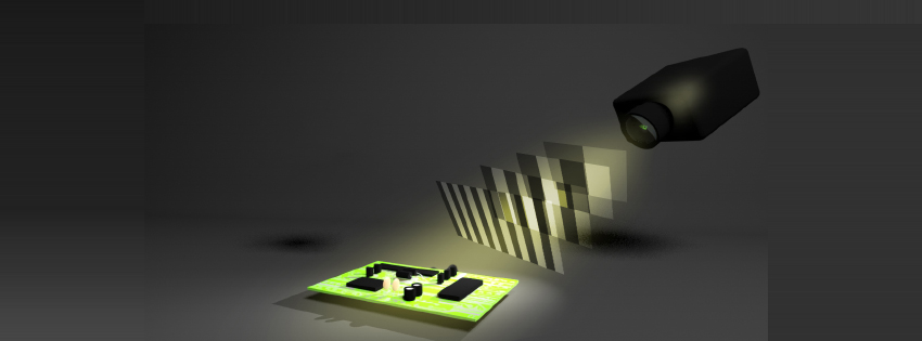
In this approach, light generated by a source at one position is used to illuminate an object, and the illumination of the object is observed by a sensor or camera from another position. If the orientation and position of the source and sensor are known, a simple triangulation algorithm can be employed to locate the point in space where the source light strikes the object. When using a single, collimated laser as the source, the laser beam must be scanned across the object space, and the sensor must be synchronized with the scanning such that each frame captured by the sensor contains but a single point in the scanning process. This approach to making the measurements is limited to one data point per frame, and thus is relatively slow in capturing data.
A more efficient approach is to project a pattern or series of patterns of light, such as a grid or a line, onto the object rather than a single point. By doing so, the sensor can capture data on many points simultaneously, and thus the number of points per frame that can be computed and added to the model increases significantly. Common patterns are lines, wire grids (vertical and horizontal lines), black and white stripes, phase-shifted gray-scale sinusoidal patterns, and a static structured pattern of pseudo random dots of different diameter (used by Kinect). Producing the more complex patterns requires either a very fast mechanical scanner to direct the laser beam over the surface or a projector that can produce the entire image at once without the need for scanning. The more complex systems utilize graphics processing units (GPUs) to take advantage of the highly parallel nature of the algorithm used to reconstruct the image from many simultaneously performed measurements.
There are several advantages to the active triangulation method. Given the relatively simple and highly parallel algorithms, the method is quite fact and often very accurate if the positions of the sensor and the source, along with the source power, are properly chosen. Acquisition rates of up to 10 million points per second at resolutions as low as 50 μm have been obtained. In addition, the method has the potential to be implemented with relatively low-cost, robust components. Low cost, mobile scanning systems for use in a wide range of applications are thus possible.
There remain some challenges with the active triangulation approach. First, the depth of field is strongly limited to distances of only a few meters, with the limit imposed by the resolution of the sensor (such as pixel dimensions in a CCD camera), the resolution of the source in terms of the number of angles and/or pattern sizes that can be generated, and the emitted power. The result is that high resolution models can only be produced at short distances, with the resolution decreasing with increasing distance, and that very large objects generally cannot be digitized. In addition, the color of the object, along with contributions from the ambient illumination, can interfere with the measurement. For example, using a red source to measure a red object reduces the contrast between the light and the background making it more difficult to accurately observe and locate the point with the sensor.